Top 5 VDD Mistakes in SMT PCBs and How to Fix Them
VDD stands for “Voltage Drain Drain” and refers to the main supply voltage that powers the internal circuits of electronic components, especially in SMT PCB designs. It is the main supply voltage provided to the active components of a PCB. It powers everything from microcontrollers to memory chips. Without a stable VDD, devices cannot function correctly.
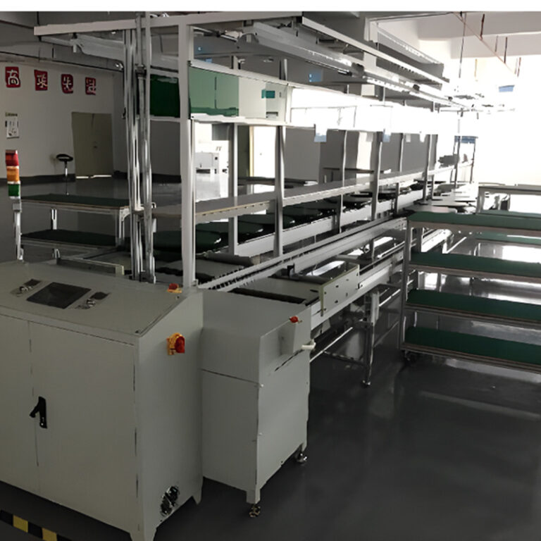
In SMT PCB manufacturing, managing VDD becomes even more important because the components are smaller, traces are thinner, and the margins for error are tighter. Therefore, even a slight fluctuation in VDD can cause serious malfunctions.
Let’s take a look at some of the most common mistakes in managing VDD on SMT PCBs and how to avoid them.
Mistake 1: Poor Decoupling Capacitor Placement
Poor placement of decoupling capacitors is a common mistake. If capacitors are placed too far from the VDD pin, they lose their effectiveness. Long traces add unwanted inductance. This inductance prevents capacitors from quickly smoothing out voltage spikes. It causes ripple noise across the board. For better results, capacitors should be placed as close as possible to the VDD pins. The goal is to create a short and direct path for high-frequency currents.
Mistake 2: Inadequate Power Plane Design
Designing a thin or fragmented VDD plane leads to unstable power delivery. A weak power plane increases resistance and introduces unwanted noise. This directly impacts the system’s performance. In SMT PCB manufacturing, a solid, wide VDD plane ensures low impedance paths. It helps to maintain clean voltage levels across the board. Always dedicate a full layer to the VDD plane whenever possible. It might seem like a simple step, but it makes a world of difference.
Mistake 3: Overlooking Bypass Capacitors
Bypass capacitors are essential tools to deal with high-frequency noise. Yet, many designs either skip them or size them incorrectly. Without proper bypassing at VDD pins, small fluctuations can build up quickly. They may even cause intermittent faults. To manage this, place multiple capacitors with different values. This helps cover a wide range of frequencies. It ensures the VDD line remains clean under different working conditions.
Mistake 4: Ignoring Trace Width and Resistance
Thin traces may seem fine on a computer screen. However, they can cause serious voltage drops during real operation. Small traces add resistance. This makes it harder for VDD to reach different parts of the PCB consistently. Especially under heavy load, the voltage at distant nodes may fall below safe levels. Always match the trace width to the expected current flow. Use wider traces or pour polygons for VDD wherever possible. It improves reliability without adding much complexity.
Mistake 5: Lack of Testing for VDD Stability
Skipping tests for VDD stability is a mistake that often shows up only after products fail in the field. Simulation during design is good, but not enough. Real-world factors like temperature, aging, and component tolerance can affect VDD performance. It is important to measure VDD ripple, dropouts, and noise on actual prototypes. Using oscilloscopes and voltage monitors helps catch hidden issues early. Testing saves time, money, and a company’s reputation.
Managing VDD on SMT PCBs might seem like a tiny detail. Yet, it holds the power to make or break the success of a product. Paying attention to VDD design, layout, and testing prevents hidden failures. It ensures that products meet quality standards every time. For SMT manufacturers, good VDD practices are not just best practices. They are essential tools for building trust, loyalty, and long-term growth.